Class Name: Reference Surface
Definition
A Reference Surface is an optional
component of a Feature Hierarchy or
Geometry Hierarchy that identifies
a surface and specifies how it is to be used to resolve the elevation
of Location 2D instances aggregated below
that hierarchy.
Primary Page in DRM Diagram:
Example
- An Environment Root has both a
Union of Geometry Hierarchy
and a Union of Features component.
The Union of Geometry Hierarchy
contains a Union of Primitive
Geometry with a Classification Data
(specifying
EDCS_CC_TERRAIN_ELEVATION).
This Union of Primitive Geometry
contains Polygons, which inherit the
Classification Data.
The Union of Features has a
Reference Surface component, which
associates to the Union of
Primitive Geometry and has these field values:
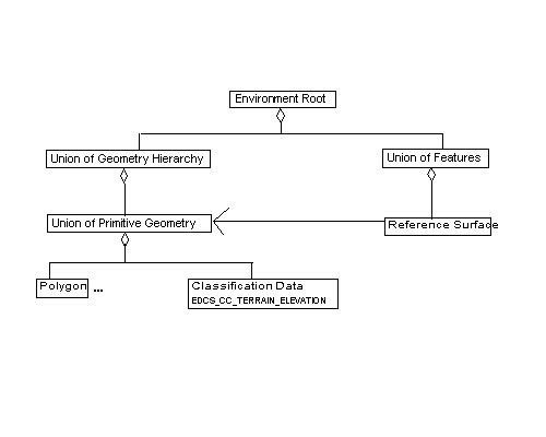
Location 2D instances found in the
Union of Features aggregation
tree use the terrain polygons to resolve elevation.
- Continuing example 1, the
Union of Geometry Hierarchy
under the Environment Root contains
another Union of Primitive
Geometry with Polygons classified as
EDCS_CC_INLAND_WATER_ELEVATION. The
Union of Features aggregates a Union
of Features, which is classified as
EDCS_CC_ENGINEERING_BRIDGE and contains
Linear Features using
Location 2D instances. The
Union of Features also contains
a Reference Surface with
Classification Data tagged as
EDCS_CC_INLAND_WATER_ELEVATION, and associated to the
Union of Primitive Geometry.
- Suppose we have, as our Reference
Surface's geometry, a
Spatial Index Related Geometry whose components are all
Classification Related
Geometry. Each
Classification Related Geometry contains 3
Union of Primitive Geometry
objects: one for terrain surface polygons, one for road
polygons (which may or may not be part of the road surface),
and one for forest canopy polygons.
The Reference Surface would associate
to the Spatial Index Related
Geometry, and its classification field would be set to
EDCS_CC_TERRAIN_ELEVATION. The resolution process then
ignores the road and canopy polygons, but sees all the terrain
polygons regardless of which union they're in.
Consider a Linear Feature
representing a road, which mostly stays on the road geometry
but sometimes strays off. This Linear
Feature is placed in a sub-
Union of Features aggregating a different
Reference Surface object, which
associates to the same
Spatial Index Related Geometry but has classification =
EDCS_CC_ROAD. The resolution
process for this Reference Surface
sees the road Polygons and ignores
the others. For Feature Nodes that
stray off the road, the corresponding
Location 2Ds' rays will fail to intersect
any road polygon, so we are in case 3: empty intersection set.
We then fall back to the previous override, which was the
terrain surface.
- Using a specific plane for elevation resolution, such as
a carrier deck, or a landing plate. Represent the plane
with one or more Polygons. Put
these A CLASS="Polygon">Polygons under a
Union of Primitive
Geometry and classify them. Use that
Union of Primitive
Geometry for the Reference
Surface associated Geometry
Hierarchy, and use the same classification for the
classification field.
- Terrain is organized in 3 minute regions, which are grouped
into 1 degree cells, where the 1 degree cells are collected
under one Union of
Geometry Hierarchy. In addition, Features
and non-terrain Geometry are organized
under a corresponding spatial organization. Each 3 minute
hierarchy has a Reference Surface
associated to the corresponding 3 minute terrain. Each
1 degree hierarchy has a Reference
Surface associated to the corresponding 1 degree terrain.
Each of the highest level feature and non-terrain geometry
hierarchies has a Reference Surface
associated to the terrain
Union of Geometry Hierarchy.
In this scheme, a Location 2D
in a 3 minute region finds
its resolution surface in the corresponding 3 minute terrain.
If a Location 2D "strays"
outside its region (i.e.,
strict_organizing_principle=SE_FALSE), then the containing
1 degree terrain resolves the
Location 2D. If the location
ray fails to intersect the 1 degree surface, then the full
terrain
Union of Geometry Hierarchy is used. If ray/surface
intersection still fails, the elevation is resolved by the
vertical datum.
FAQs
When does a hierarchy need a Reference
Surface component?
A Reference Surface isn't required
(it's optional) unless:
- there are Location 2D objects below the
hierarchy,
- the Location 2D objects are in the scope
of a 3D spatial reference frame, and
- you (the data provider) want the locations to lie on a
surface other than the last default surface (The initial
default is the spatial reference frame's vertical datum).
Why does a hierarchy need a
Reference Surface? What do you mean by "elevations" for
Location 2D objects? They don't have
elevation.
In a 3D spatial reference frame, Location 2Ds
are thought of as lying on a surface. Which surface is intended seems to
be subjective at best. A cartographer may prefer the Vertical Datum as
the Location 2D surface, while others prefer
the "terrain surface". Terrain surface is also a subjective
term, and terrain surfaces have been mapped to the SDRM in a variety of
ways. Even if one notion of surface for Location
2Ds were mandated, it would not meet everyone's requirements.
The solution is to mandate a clearly defined surface (the initial
default) and provide a flexible mechanism to override the default
for all or for selected parts of the transmittal.
How does a Feature Hierarchy or
Geometry Hierarchy use a
Reference Surface to resolve elevations
for aggregated Location 2Ds?
Consider a Reference Surface that is
associated to a Geometry Hierarchy
that contains a surface. A Location 2D
corresponds to the (unique) ray which is:
- Normal to the surface of the SRF
ellipsoid*,
- Intersects the ellipsoid at the same horizontal coordinates as the
Location 2D, and
- Extends below the surface of the ellipsoid to a depth equal to the
minor radius of the ellipsoid.
(*
NOTE:
For augmented Projected SRFs, this is the projection ellipsoid.
For LSR, use the z=0 plane, where z is the coordinate axis
specified by the SE_LSR_3D_PARAMETERS up_direction value.
)
The intersection of this ray with the resolution surface defines the
candidate set for the corresponding 3D location. One 3D location is
selected from the ray/surface intersection set according to the
following three cases:
- If the set contains 1 and only 1 element, the spatial position
of that point resolves the Location 2D
instance.
- If the set contains more than one element, the
Reference Surface field
multiplicity_rule value is used to select exactly one element.
(For instance, if several overlapping Property
Grids with Grid Overlap components are
part of the Reference Surface, use
Grid Overlap's rules to define the
Reference Surface in the overlap
region of two or more of the surface grids. If the intersection set
still has more than one point, use multiplicity_rule.)
- If the intersection is empty, then look for other
Reference Surface objects higher up
the aggregation tree and repeat this resolution process with that
surface instead. If there are no other
Reference Surface objects higher up
the aggregation tree, then use the vertical datum, which is guaranteed
to be a case 1 surface. (See also example 5).
How do a Geometry Hierarchy's and
Reference Surface's field values define
a surface for the resolution process?
There are several cases:
- The Geometry Hierarchy is a
Property Grid Hook Point that
aggregates at least one Property Grid with
these qualifications:
- its data_table_type field is equal to the
Reference Surface's classification field,
- it has 2 spatial axes corresponding to the horizontal coordinates of
the SRF, and
- it has a Table Property
Description for height, elevation, or bathymetry.
If the Property Grid meets the above
criteria, then it defines a resolution surface.
- The Geometry Hierarchy is a
Union of Primitive Geometry
that aggregates Surface Geometry with
Classification Data matching the
Reference Surface's classification field.
In this case, all such Surface Geometry
objects combine to form the resolution surface. (Note that the
multiplicity_rule field deals with surface complexity).
- The Geometry Hierarchy is a
Distance, Index, or Map Scale
Level of Detail Related
Geometry that aggregates (directly or indirectly)
Geometry Hierarchy cases 1 and/or 2
above under an LOD branch selected by the
Reference Surface lod_rule field.
- The Geometry Hierarchy aggregates
some combination of cases 1, 2, or 3.
In general, the set of all Surface
Geometry and Property Grids under the
Geometry Hierarchy is culled by
matching the Reference Surface
classification field (and Property Grid
qualifications) and matching LOD branches to the lod_rule field. The
remaining geometry is the resolution surface used for ray intersections.
What if there is no single
Union of Primitive Geometry that defines the
Reference Surface?
There is no requirement that the aggregate be free of non-reference
surface geometry (See example 3). In this case, find the higher level
Geometry Hierarchy that aggregates the
desired Union of Primitive
Geometry sub-hierarchies, and use that for the
Reference Surface association.
What happens to LSR Location 2D
objects in an LSR Model when the
Model is instanced by a model instance object
in a non-LSR 3D spatial reference frame?
That depends on whether or not the scoping SRF supports
Location 2Ds.
- If Location 2D objects are supported in
the scoping SRF, (e.g. the scoping SRF is 3D geodetic, for which we
have 2D geodetic), these LSR Location 2D
instances are converted to Location 2D
objects in the instancing 3D SRF using a 3 step process:
Step 1) An LSR Location 2D is converted
to LSR Location 3D by resolving
to the LSR vertical datum (z=0 plane, where z is the coordinate
axis specified by the SE_LSR_PARAMETERS value up_direction).
Step 2) The resulting LSR Location 3D is
converted to a Location 3D in
the scoping 3D SRF in the usual (model instance) way.
Step 3) If the SRF supports Location 2D
objects (e.g. geodetic), then the
Location 3D is collapsed to a
Location 2D with the same horizontal coordinates.
- Otherwise, if the scoping SRF does not support
Location 2Ds, then the
LSR Location 2D is converted to 3D
by setting the tertiary axis value to zero.
(Note 1): LSR models may not contain
Reference Surface instances. See
constraints.
(Note 2): Conformal behavior may also be modeled with
LSR Location 3D Control Links.
Can a Geometry Model Instance
be used for a Reference Surface
association?
Yes, if the Model's spatial reference frame
matches the currently scoped 'world' spatial reference frame.
How are Location 2D instances converted
consuming data in a different spatial reference frame?
There are two cases.
Case 1 - both SRFs have the same horizontal datum.
Case 2 - The two SRFs have different horizontal datums.
In case 1 (Same horizontal datum), the ray determined by the
Location 2D is invariant, so the horizontal
coordinates are converted in the usual way.
In case 2 (Different horizontal datums), the ray may change, so three
steps are needed:
Step 1) Resolve elevation in the originating SRF and convert the
Location 2D to
Location 3D.
Step 2) Convert the Location 3D to the
second SRF (conversion not currently supported).
Step 3) Collapse the Location 3D to
a Location 2D.
If I consume a transmittal in different SRF, should I resolve
elevations in the originating or the consuming SRF?
It should not make a difference if the two SRFs are both
"real world" or both Augmented Projected Coordinate Systems
(APCS). In the case in which one is "real" world and the
other is APCS, there are two ways to deal with the
"conversion distortion" that tends to bend flat surfaces.
Consider a Location 2D whose ray intersects
the resolution surface near the center of exactly one triangular
Polygon. The intersection point determines the
elevation, and therefore a corresponding Location
3D. If you resolve in the first SRF, and then convert the
Location 3D, the location will match the
transmittal point, but it may no longer lie on the triangle's surface.
On the other hand, if you convert the Location
2D and then resolve in the second SRF, the corresponding
Location 3D will lie on the triangle's
surface, but may differ a little in elevation from the originating point.
Therefore if absolute location is more important than conformality,
then resolve in the originating SRF. If conformality is more important,
then resolve in the consuming SRF.
Constraints
Associated to (one-way)
Component of (one-way)
Notes
Associated with Notes
 indicates that the <Geometry Hierarchy> contains the <Surface
 Geometry> and/or <Property Grids> to be used as the resolution
 surface.
Fields Notes
 rule to select a single point from multiple intersections of a
 ray with a resolution surface
Use only geometry with this classification
 All, most detailed, least detailed, ....
 rule to select one LOD branch.
Prev: Reference Origin.
Next: Reference Vector.
Up:Index.